Network Processors and CompactPCI
JEFF MUNCH
2003/04/18
One of the more specialized processors in today's marketplace is the network processor. This processor is intended to manipulate packet based data at line rate speeds. Over the last few years, silicon vendors have been actively touting network processors over ASICs in WAN edge/access aggregation, wireless infrastructure and Layer 4-7 switch applications. This article will take a look at some of the PCI Industrial Computer Manufacturers Group (PICMG?) standards that are typically used with network processors. An application that converts ATM to IP will be used as an example.
Network Processor Data Transport Interfaces
When using network processors in standards based CompactPCI platforms, one of the first challenges is how to handle the data transport interfaces that a network processor provides. Network processors typically use packet based interfaces to connect PHY devices. Some of the common interfaces are Universal Test and Operations PHY Interface for ATM (UTOPIA), Packet Over SONET PHYsical (POS-PHY) interface, and System Packet Interface level 3 (SPI-3). To complicate matters further, some of the interfaces support multi-PHY mode which allows an interface to support multiple PHY devices. As you can see, the type of interface used for the main data path on network processors is significantly different from the PCI bus used in traditional CompactPCI boards. Early adopters of network processors on CompactPCI recognized the need to provide a flexible interface that could support the packet based data transports of the future. The following block diagram is an example of the types of interfaces that a design might have to contend with when using an Intel IPX2400. Note that many network processors allow the interfaces to be configured to support a variety of different transports. This is only an example of one possible configuration.

In the example above, the Utopia Bus will ultimately connect to an ATM PHY device
and the SPI-3 interface will connect to two Ethernet PHYs for the IP traffic.
An I/O mezzanine will be used to provide the ATM PHY connection providing
flexibility in the type of PHYs that can be used.
I/O Mezzanines
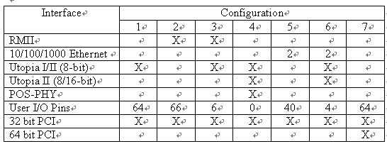
CompactPCI and VME board developers often use PMC sites as a method to provide additional I/O capability. PMCs can be added to the board to augment the I/O payload of the board. Typical PMCs include mass storage, network, and general purpose I/O. The PMC specification uses the PCI bus as the interface between the board and the PMC module. PCI was chosen as the interface because of its ubiquitous nature; almost any I/O function desired could be found with a PCI interface. The PMC interface has served the CompactPCI and VME markets well, but lacked the packet based data transport interfaces required by network processors. In August 2001, PICMG released PICMG 2.15 PCI Telecom Mezzanine Card (PTMC) specification. This specification was intended to support 4 popular industry standard telecom bus interfaces (H.110, Utopia Level 2, POS-PHY, and RMII) as well as support for the existing 32 and 64 bit PCI bus. PICMG released an ECR to PICMG 2.15 at the end of 2002. This ECR expanded the number of configurations supported from 4 to 7 by adding Ethernet capabilities to TDM and UTOPIA configurations. The flexibility provided by PICMG 2.15 comes at a price, namely ease of use. The PICMG 2.15 subcommittee had to live within the pins available in the PMC specification. This limitation required that specific configurations and pin usages be documented and also required that the pins traditionally used for the upper 32 bit of 64 bit PCI interface be redefined to support the new I/O capabilities limiting PTMCs to 32 bit PCI interfaces. When using PTMCs it is important to verify that the PTMC and board it plugs into (carrier card) support the same configuration. The table below defines at a high level some of the PTMC configurations available.

The capabilities of a PTMC and Carrier Card are determined by its configuration
type. As an example, a PTMC and Carrier Card that supports configuration
5 (2 Ethernet and 32 bit PCI interfaces) is referred to as a PT5MC and the
Carrier Card as a PT5CC. It should be noted that the number of PMC I/O lines
available to support rear I/O is impacted by the various configuration types.
When selecting the type of PTMC take into consideration the interface and
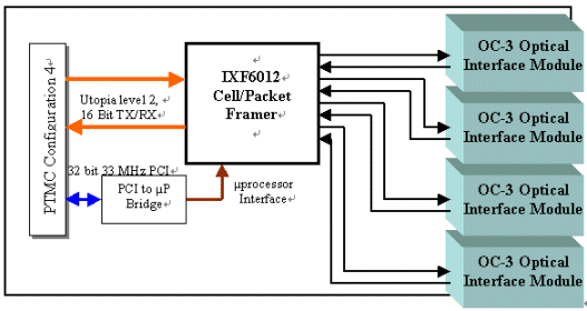
rear I/O requirements. Lets take a look at a block diagram of a PT4MC that
provides quad OC-3 interfaces and uses Utopia level 2 as the interconnect
to the network processor.

In this example the Utopia Bus is the primary data path for the packet based
data traffic. The PCI bus is used to configure and control the IXF6012.
By using a PTMC designers can provide flexibility in the types of PHYs that
can be connected to a network processor card.
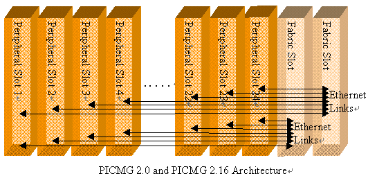
PICMG 2.16
The next piece in this design is the IP data transport. This transport should provide redundant Ethernet links for fault tolerance and enough bandwidth to handle the required traffic. In September 2001, PICMG approved the PICMG 2.16 Packet Switched Backplane specification. This specification defines dual10/100/1000Mbit Ethernet interconnects for CompactPCI boards. PICMG 2.16 compliant systems have been deployed in a variety of applications. The ubiquitous nature of the Ethernet interconnects and the need for IP data transports has led to high levels of adoption among system providers. The figure below shows the IP connectivity. It is interesting to note that this example removes the PCI bus from the CompactPCI system. The industry is starting to see a migration away from PCI and towards IP for connectivity in platforms that handle IP based traffic. This is an example of a possible implementation.

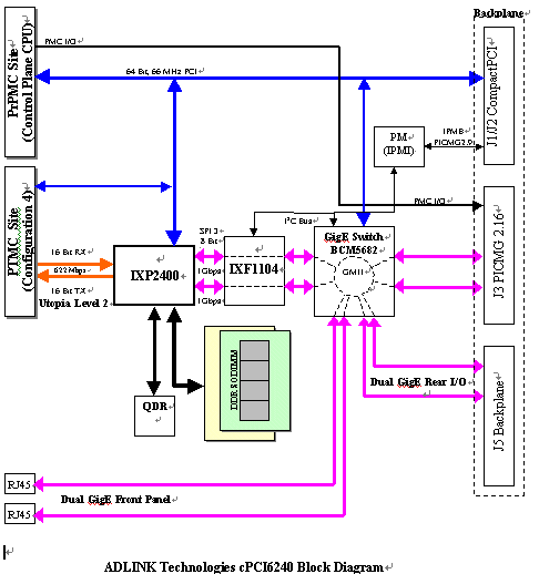
In architecting a CompactPCI board that converts ATM to IP one might want to
add some flexibility beyond what has been discussed. In many cases, the
application might require additional general purpose processing power to
handle exception packets. An additional PMC site could be added to support
a processor PMC. It is also likely that a user might want to access the
IP traffic from the front of the board for test. Front mounted Ethernet
connections might also be used for boards that need to route IP traffic
only. In this case, the PTMC would not be used. A block diagram for a flexible
general purpose network processor blade is shown below.

Summary
Network processors are here to stay. Industry standards that exist today and that are currently in production can be used in applications that require manipulation or routing of packet based data. Some of the applicable standards are PICMG 2.0 CompactPCI specification, PICMG 2.16 Packet Switched Backplane specification, and PICMG 2.15 PCI Telecom Mezzanine Card specification. In the example given, ATM cells are buffered by the framer on the PTMC card. The PTMC and network processor board use the Utopia Level 2 to transfer the data to and from the PTMC and the network processor. The Ethernet switch and PHYs provide redundant links for the 2.16 IP traffic. The one missing piece of the puzzle is Automatic Protection Switching (APS). Most applications that handle ATM require redundancy at the card level. This requires that two network processor boards share state information so that in the event of a failure, the standby network processor board can take over with minimal lose of time or data; this is an exercise left to the reader.
凌华科技供稿 CTI论坛编辑


